The Picofox Saga: Chapter 2 - Revenge of the Spurs
February 6, 2026
This post was supposed to be short, just a quick update to say “I made a better PicoFox”. It was supposed to be a marketing piece driving sales, expressing gratitude to the community for great feedback, etc, etc, etc. What foolish thoughts I had!
Instead this post is a 1,691 word discussion of dumb decisions and the frustrations of engineering tradeoffs. Also, I made a better PicoFox.
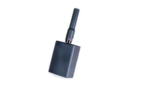
PicoFox r3
Let’s get the good stuff out of the way. I did make a better PicoFox. The first PicoFox I sold was revision 2. You can read more about that in the first chapter of The PicoFox Saga. Customers, friends, and the community at large provided great feedback.
A few things I should have known:
- USB-C is better than Micro-USB.
- Devices should charge even if they are off.
- Charging indicators are useful.
- Aesthetics aren’t the most important thing, but they are important (commentary on the print quality of my enclosures was very politely phrased, and I am grateful).
Some things were less obvious:
- Adjustable power output is actually very important for small foxes. Power output has a huge impact on difficulty, not just range.
- More range (i.e. higher maximum power) is needed for geographically interesting locations.
- The battery could be a bit bigger. Five hours is good, but 8+ would be better.
Some things I could have learned in school:
- Edge mount SMA connectors are way better than through hole.
- ESD protection on external connections is a really good idea.
- Sectioning and fencing off RF sections reduces cross-talk and spurs (okay, I knew this, but I didn’t understand or implement it).
All of that and more went into designing r3:
- Increased power output to at least 65mW (18.1dBm), under ideal conditions full output is about 80mW (19dBm).
- Added a programmable attenuator enabling power reductions in 1/4dB steps down to under 1mW.
- Improved DFM (design for manufacturing). This was mostly replacing THT components with SMD equivalents. (The savings from this covered the cost of the new amplifier and attenuator.)
- Improved the layout for better spur suppression, reduced cross-talk, and more stable power delivery.
- USB-C charging, with a charge indicator and (gasp) charging while off.
- SMA connector replaced with an edge launch version. In addition to the objective RF performance improvements this made enclosure design much simpler.
- ESD protection added to USB data lines and the antenna connection. (None of my r2 devices have failed due to ESD damage but I do think I made at least one EE cry.)
- Designed a beautiful injection molded enclosure to replace the rough 3D printed original. (It’s also more durable and made from ASA for UV resistance.)
- Doubled the battery capacity. Even with the increased power output the new battery lasts 10+ hours at full power and duty cycle (and that’s before optimizing the software to use less power, which I have added to future-Justin’s to do list).
There’s probably more but that’s what I can remember. Unfortunately this is where the “good” part of my post today ends. Keep reading for the “bad” and the “ugly” or stop here and pretend that I’m an amazing engineer who never does silly, unwise, or downright stupid things.
The Bad
First, after the massive amount of rework that was required on r2 boards I was really hoping not to need any rework for r3. I even sent my schematic and layout to a professional for review. They did a great job but they (and I) missed an LED which had an incorrect footprint. The other two had been updated to the correct footprint but the third LED was reverse biased.
The second issue was entirely me. My reviewer suggested adding a transistor to control power to the 3.3V regulator, rather than switching mechanically. This was a good idea as the worst case load was approaching the switch’s rating. Unfortunately I put the transistor in circuit with the drain and source pins reversed. As a result the transistor has no off state, it’s basically just a body diode burning 0.7V. It was such a simple change that I didn’t send the updated schematic for review or fab’ another prototype.
That last sentence is really important. I made a change to the power supply circuit without spinning another prototype or even having the change reviewed by anyone other than myself. Past-Justin is an unrepentant gambler who never learns from his mistakes (current-Justin is a disciplined professional who would never even consider taking such risks).
Five hundred boards were assembled with a backwards LED and an always-on power transistor.
Solutions
The LED isn’t a hard fix. Just heat it up, take it off, rotate it, and put it back. It’s a side-mount package so slightly more challenging but after a bit of practice I was able to do this rework quickly and consistently.
The transistor is harder. There is no SOT23 transistor that has the reversed pinout so there is no device I could buy and swap out. For a while I thought this mistake would mean scrapping 500 boards or cutting traces and wire to fix it.
Then I had a stupid thought. Why not make an adapter PCB? We make small boards that host some chip and expose it’s pins all the time. We even make adapters that convert between one pin-out and another. They are usually bigger than a few mm on each side, and usually adapting between a smaller footprint and a larger one, but we do this all the time.
Many board houses won’t make a board this small but it turns out JLC PCB will, and they’ll even panelize them with clean V-cuts (if you put enough of the tiny boards on a panel so they fit in the V-cut machine). The design is simple - a PCB just barely bigger than the transistor’s footprint that can be reflowed onto the existing footprint and then just switch the pins in the traces / vias between the two layers. It took 5 minutes to design. (If you ever make this mistake (based on some interesting threads on Reddit I’m not the only one) I put the adapter board on GitHub.)
To my shock and relief when the boards came in this dumb idea worked perfectly. I developed a quick routine - flux, hot air, remove transistor, place adapter, place transistor on top, more flux, wiggle it to check for good joints underneath.
Rinse, repeat, rinse, repeat… drift into a monotony induced trance and stare into the unfeeling void… rinse, repeat… 489 boards later I ran out of flux.
Two days and a new batch of flux later 500 boards were successfully reworked. They’ll all be thoroughly tested before assembly but so far only one was irreparably damaged - I killed an LED by giving it too high of voltage trying to test it. I’ll keep that PicoFox for myself, I don’t need a transmit LED anyway.
The Ugly
Spurs. Every radio has them. r2 had them and I had to turn down the power to meet regulations (still made my 15mW goal though). r3 improved those spurs but the si5351 creates distinct dithering spurs when generating clocks at VHF. At full power they are just a couple of dB under the 10uW requirement by the FCC ( 47 CFR 97.307(e) ). That’s good but part of my design for r3 includes an upgrade footprint on the back. I intend to create an extra amplifier stage for folks that want 1W+.
I spent a truly inordinate amount of time tinkering with this. The si5351’s documentation doesn’t really discuss these spurs or how to manage them. For a while I thought I had an oscillation in the power supply to the chip which was mixing to create the spurs. That would have been an easy fix, but no such luck.
There is some mention of jitter in the datasheet, of course, and that is the source of the spurs. Generally speaking dithering spurs disappear when both the PLL and MS are in integer mode but increase with frequency if either system is in fractional mode (as it must be to accomplish frequency modulation at VHF). Interestingly the spurs nearly disappear below about 100MHz.
Overall there’s not much that can be done to improve the current hardware but it does meet regulatory requirements.
Solutions?
Without changing the base PicoFox there’s a lot that can be done on future upgrades. Additional filtering is the likely solution, perhaps a switchable array based on the carrier frequency. Using software to modify the PicoFox’s behavior when a MegaFox amplifier is present is another option. The MegaFox could take a lower frequency which is a harmonic of the desired output, or even take an intermediate frequency and mix it to the target band.
Something will need to be done, but there are options. Since the dithering spurs are very close to, even sometimes inside, the amateur 2m band filtering is a challenge. Whatever the final solution is that change can be moved down to the PicoFox itself in future revisions.
Until Next Time
That wasn’t the happy ending I’d hoped for, but engineering is just trade offs and challenges all the way down. r3 is an amazing design that I’m very proud of. r4 will be better (please don’t wait for r4 to buy one, I have 500 of these things and I genuinely can’t make r4 until I sell most of them).
Stay tuned and join the email list for early updates. The 1W+ MegaFox upgrade is coming, rest-assured it will be available as an after market upgrade.
My sincere thanks to everyone in this community who gave me feedback on the PicoFox, whether you bought an r2 or just shared your thoughts. I couldn’t do this without that support. I don’t want anyone to feel like they miss out when they buy an early version and then I make improvements - if you have an r2 send me an email for a $10 discount on the r3.
73, AI6YM