The PicoFox Saga
August 16, 2025
Have you ever had an idea so spectacularly dumb you had to make it happen?
After seeing several SI5351 based transmitters for HF I had the idea that maybe this chip could be pushed to do frequency modulation on VHF bands. It does glitchless frequency changes, it can generate VHF clocks, it even claims a 0 PPM error. We all know that last part is nonsense but the error is so low that we can pretend that it’s zero and just select an appropriate input oscillator.
This is a spectacularly dumb idea. There are a hundred better ways to implement frequency modulation from simple analog circuits to full software defined radio. This is a middle ground that no one asked for but the idea was just so tempting to me and I couldn’t find a single technical reason not to do it.
I won’t bury the lede – I built the darn thing and it’s a great fox transmitter. Easy to configure just by editing a text file, extra GPIO for adding external devices, open source hardware and software so you can tinker to your heart’s content. It’s great, you should buy one. They’re in stock and shipping right now.
Of course, whether you buy one or not you should read on. Actually building this thing was quite the journey.
Project Goals
Torturing a ‘5351 into performing frequency modulation wasn’t my only motivation for this project. I love fox hunts and I’d been wanting to explore VHF circuit design for some time. A few friends had mentioned that they wanted to tinker with fox transmitters – adding extra functionality or behavior but none of the commercial options offer much freedom. Everything is closed source and locked down, it makes no sense to me but apparently it makes business sense since we see this pattern everywhere.
With that in mind my design goals were as follows:
- Frequency agile within the two meter band.
- Customizable audio output, including auto-generated ID.
- Configuration without special software, apps, or terminal emulation.
- At least 12dBm (15mW) output, higher powers and adjustable output would be nice not required.
- Allow for expansion, tinkering, and the like.
- At least four hours runtime at 100% duty cycle.
- Retail price under $100 – less than comparable closed-source products.
This is the saga of the PicoFox, an open source fox transmitter built around an SI5351. It’s my first foray into the world of VHF circuits but it will not be my last.
Hardware is Hard
While the design goals above were met it was not an easy path. I’m a software engineer with no formal training in electrical engineering or RF. I hardly have formal training in software and I do that for a living.
r0

My first prototype is hardly worth mentioning. I went with an AVR microcontroller that could never pull its weight. Just getting the ‘5351 up took most of the flash. The thing might be a decent paperweight if I cast it in resin but it’s useless besides that.
r1

My second prototype gave me the name. I upgraded the MCU to the absurdly overpowered, yet surprisingly inexpensive, RP2040. The PicoFox r1 board was still DOA. My gerbers included a ground island around the ‘5351 and I left off the RP2040’s reference crystal. With a bit of rework and a lot of time hacking around the MCU’s initialization code the circuit came to life.
Leaving off the reference crystal was intentional. I designed the board with only the 25MHz TCXO for the ‘5351 thinking I could use an extra clock output for the RP2040. The RP2040 datasheet claims it can run off the internal ring oscillator and that’s theoretically true. I planned to bring up the ‘5351 as an accurate external clock during the bootstrap phase.
Unfortunately the folks who wrote the bootloader code did not make this easy. The bootloader is read only from the factory and assumes a 12MHz crystal is present. It’s possible to bootstrap over the debug interface but USB programming will never work with this method so I scrapped it and put the crystal back on the board in r2.
Needing a cheap crystal on the board right next to my beautiful TCXO and the ‘5351 with unused clock outputs annoys me to no end.
r2
Then we have r2. My first production run. I had the software for modulation working, I’d tested the filter design, the amplifier circuit was working as expected, and I had run the DRC about forty times to make sure I didn’t leave a ground island again.
I created the production order, uploaded my Gerbers and BOM, paid for fifty boards, and quickly realized that I’d made several mistakes in my BOM.
- The voltage regulator had far too much dropout for the board to have any runtime on a LiPo battery cell.
- One of the filter inductors was the wrong type, leading to high losses and unstable performance.
- The amplifier bias was passing through a ferrite rather than a wirewound inductor, leading to lower than expected amplification and further losses.
- Coupling capacitors were of the wrong type and the wrong value.
- As if to insult myself further I forgot to add a power switch to the darn thing.

It was too late to cancel the order. Most of my mistakes weren’t that hard to fix. I ordered the correct LDO, filter inductor, amplifier bias inductor, and coupling capacitor to arrive before the boards. It’s not exactly fun reworking 0402 components but I can do it. I just set up my workstation, blasted some tunes, and got it done.
The missing power switch was a bigger problem. I ended up designing a tiny circuit board that connected to the PicoFox PCB on the battery header. All it can do is interrupt the connection to the battery which means that the r2 can’t be charging and off at the same time. Power from USB will turn the transmitter on regardless of the state of the battery switch. It’s not the best design choice but it’s far better than having to disconnect the battery to turn the thing off.
Software is Easy
Software struggles were surprisingly simple for such a marvelously stupid idea as frequency modulation from software through a programmable clock generator. The RP2040 is more than fast enough to do the necessary flash operations and mathematics. Getting the ‘5351 to update fast enough was just a matter of running the I2C bus at ludicrous speeds.
I’m joking, I’m only running I2C at the absurd speed of 1MHz and I could probably make it work at 800kHz. Audio is modulated at 5kHz giving a nyquist frequency of 2.5kHz, more than enough for decent quality audio or even speech.
Sharing a single flash chip for both code and data was a bit more challenging but the Adafruit TinyUSB library had solved most of the problems. Dual access to a FAT filesystem is less fun, it’s fairly easy to corrupt data if either side executes a write operation while the other is reading. (It’s nearly certain that concurrent writes will corrupt everything.) I solved this just by detecting writes and turning off the transmitter when a PC is writing to flash.
The Etherkit SI5351 library I chose didn’t require any modifications but I did have to do a bit of the work myself to enable glitchless updates. You can see in the code on my GitHub that I’m skipping a lot of the more user-friendly library methods and jumping straight to the lower layers. That’s fine with me but it was very frustrating to see that the library is incorrectly documented. Multiple methods describe an input in Hertz when centi-Hertz are actually needed. Figuring out why I was generating signals at 1/100th my target frequency took a bit of time.
In the end the software works. Modulation looks good, spurious emissions are low, and the transmitter can be configured just by editing a text file. There’s definitely a few places that the software could be improved but I’m very happy with it as is.
For the curious readers in time I plan to improve the following:
- Apply configuration and other changes over flash without power cycling (and turn the transmitter back on).
- Smooth out modulation to reduce artifacts (some clicking and buzzing sounds are present). The issue seems to be because the Etherkit library uses a fixed denominator for fractional PLL and MS math. I suspect this may reduce the small spurs I see in the spectrum as well.
- Upstream board support in the Arduino Pico package.
- Correct Etherkit library documentation and merge upstream.
All Measurements are Estimates
Of course I needed to thoroughly test the RF performance, this was my first VHF project after all. I needed to know how good my filters were, whether I reached my target output power, and if I kept spurious emissions low enough to meet US 47 CFR 97.307(e) (and similar international regulations).
That’s where the fun began. My TinySA produced reasonably accurate results under 350MHz, it was off by a couple of dB but probably could have just been calibrated better. In high mode, above 350MHz, the data was nonsense. Regardless of my power output, inline attenuators, etc I measured -32dBm 3rd and 5th harmonics whenever the transmitter was on. That’s quite high given the seven element LPFs I had on the board and the performance of them measured by my NanoVNA. It also makes no sense that the levels stayed the same when reducing power or adding inline attenuation.

 2nd and 3rd harmonics.")
It turns out that this was all nonsense created by TinySA’s own harmonic distortion. I borrowed a much better (and out of my price range) Siglent SA from a dear friend. That device measured 3rd and 5th harmonics lower than -60dBm. Better than I had expected and essentially silent (good luck using the 3rd harmonic trick to find this fox!)
Output power was a bit higher than expected and spurs were detectable at about +/- 1MHz. With the ‘5351 turned down to its lowest power setting the spurs are well below the FCC requirements and the fundamental power is still better than my design goal of 12dBm. It would be nice to squeeze a bit more out, 17dBm is possible at higher ‘5351 currents but the spurs exceed FCC limits.
Antennas, Really?
After all that. Mistakes in prototypes, production board rework, software hackery, and a TinySA pulling nonsense numbers out of its rear port, the most difficult thing was finding an appropriate antenna for this product.
I’m serious. I didn’t need or want a massive antenna for a fox. The performance benefit isn’t worth it but the additional shipping cost would raise my prices. I found some little stubby antennas with terrible performance and some nice options in the middle. The middle options were out of stock, absurdly priced, only offered the wrong connector, or could not be shipped to the US for unknown reasons.
I spent weeks searching. In the end I ordered a bunch of nearly 16” (40cm) whip antennas which all got lost in shipment somewhere in Kansas. When I went back to reorder the smaller antennas were in stock.
Great, that’s a win even if it delays launching the product a bit. Eventually the longer antennas I ordered were found (in a cornfield, I’m guessing) but were the wrong connector. The supplier refused to take them back but did ship me the correct antennas. I couldn’t make this up if I tried.

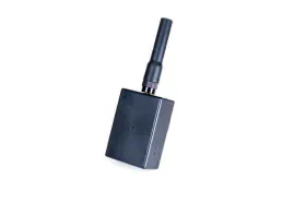
The PicoFox is shipping with a great little antenna, it’s flexible and performs quite well for its size. I also have two boxes of antennas that I don’t need but I’ll solve that problem another day.
Wrapping Up
This was a fun project. I created a great little fox transmitter that’s easy to configure and can be modified by tinkering hams to be whatever they can think of. Folks who dropped by my booth at Hamvention and FDIM got to see the r1 prototype. The response from everyone was encouraging and I even took a few preorders.
I can’t wait to see what this community comes up with. Take a look at the PicoFox’s page if you’d like to learn more about the final result of this work. You can order one from that page too, whether you want to hack it into something amazing or just enjoy an afternoon fox hunt.
73, AI6YM
p.s. I really do have over a hundred antennas I don’t need. Nagoya model NA-771 with either the SMA male or SMA female connector. Yours for cost and shipping if you’d like to help me get some out of my shop (email me – justin@ai6ym.radio). It’s a good HT antenna, I just don’t need 100 of them.