
The FoxSniffer Chronicles - Chapter 2 - Good Ideas & Bad Results
November 8, 2026
In the last chapter I showed you the r0 prototype
paperweight and all the various challenges with it. The next step was basically a complete
redesign.
This chapter covers the prototypes and tests between the r0 and r1 hardware versions. r1 is next full prototype and will be covered in more detail in the next chapter.
Spoiler - I did eventually make a good receiver and shipped it! The r3 hardware is currently in stock and on my store - you should buy one!
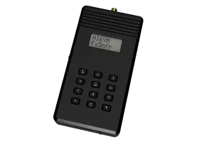
To refresh your memory - r0 didn’t have a real receiver, just a signal strength meter. Your feedback told me that some use cases will require demodulating audio so I need a real receiver. (Software for that feature is still under development.) Testing on the prototype showed that my board layout leaked a lot of noise into the incoming signal, severely impairing sensitivity. The circuit I had was essentially scrapped and I started again.
Let’s get in to it.
Prototyping in Modules
Rather than creating another complete prototype I decided to build each section of the circuit on a separate module. I didn’t need a UI to validate the RF circuit and modules would let me work faster (ha ha ha). This strategy would also make my mistakes less expensive.
The modules were designed to be testable in isolation but then chained together to evaluate the combined circuit.
Designing an SDR
I was initially hesitant to build an SDR for VHF and UHF. That’s not an easy task and I felt like it would be too much to take on - until I realized that I had already built this receiver! The T41 kits I offered last year and the T42 designs I’m working on now use a Tayloe Detector (quadrature sampling detector) that works up to 54MHz. I know my way around this type of circuit and have built several functioning variations of it.
Making that same circuit work at VHF and UHF should only require mixing the incoming signal down. My r0 prototype included a working mixing stage - I messed up a lot of things around that mixing stage but the mixing itself worked fine.
Choosing IFs & LOs
The SI5351 clock generator is still the heart of my circuit, it can generate three (mostly) indepedent clocks up to 200MHz. I briefly entertained other clocking options but decided this chip was still the easiest way to make this receiver work.
The 200MHz limit means that I’d need at least two mixing stages. The last IF would need to be 50MHz (each mixing stage can only move the signal by the maximum LO). This also means that I need multiple preselect filters before the mixer. If the target signal is at 450Mhz with a 200MHz LO images will be at 250 and 650 - so those need to be filtered out before the mixer. To also support lower frequencies I need another filter or perhaps several that could be switched in and out.
I’ll save you the details - there’s a lot of over complicated ways to do this. I wanted 100-450MHz continuously but that would have required switchable filters on the frontend and after the first mixer. Looking at the FCC frequency allocations there isn’t much interesting in the 225-275MHz range so I decided I could sacrifice that band to the IF gods.
My final IF plan became this - fix the first IF at 250MHz. 100-225MHz can be mixed up while 275-450MHz is mixed down. The 50MHz dead band gives plenty of room for filter roll off.
Having the first IF at 250MHz means that a single bandpass filter after that mixer cleans up the band, and the second IF can be fixed at 50MHz into the Tayloe Detector. Only two preselect filters are needed and no switched filters are necessary after the preselects.
Arranging the Mixing Stages
For these module prototypes I continued to use the ADEX-10L+ mixer from MiniCircuits. The datasheet covers the full range of frequencies I wanted to cover and it’s quite simple to use. The problem with this device is the cost, and being a passive device it requires extra amplification stages adding even more cost.
I ended up switching to an active mixer in r1 and later. More on that in the next chapter. The architecture is the same.
After the preselect filters and attenuator ladder the signal goes through an LNA to counter losses in the mixer, then the signal is mixed to the first IF using a variable LO from the SI5351. A bandpass filter cleans up the output signal before another LNA.
The second mixer mixes down to the second IF with a fixed LO, the output goes through another bandpass filter and another LNA before the Tayloe Detector.
Building the Tayloe Detector
The details of a quadrature sampling detector (QSD) are beyond the scope of anything I feel I could write with any accuracy so I’ll give you links instead:
- Dan Tayloe’s original paper Ultra Low Noise, High Performance, Zero IF Quadrature Product Detector and Preamplifier is the definitive source for actually understanding this circuit.
- A Software-Defined Radio for the Masses by Gerald Youngblood (AC5OG) is a great starting point for anyone wanting to actually build one. The references and notes at the end are very useful.
- I also highly recommend Digital Signal Processing and Software Defined Radio: Theory and Construction of the T41-EP Software Defined Transceiver by Al Peter (AC8GY) and Jack Purdum (W8TEE). It’s a fantastic guide to building a fully functional transceiver, including software and hardware, around the concept of quadrature sampling.
In essence the circuit works by switching the incoming RF (now at 50MHz thanks to the mixing stages) into four samples separated by 90 degrees of phase. I and Q channels are built by treating pairs of the switched samples as differential signals. It’s a mixing stage with image rejection built in that brings everything down to baseband. From there common op-amps, ADCs, and audio frequency gear can process the signals and bring them into the digital domain. This is not a detector or demodulator circuit in the traditional sense - the data coming out is the RF signal mixed down, not demodulated audio.
The circuit needs a switch that can handle the switching frequency - a lot of inexpensive mux/demux chips can do that these days, some amplification and filtering - an op-amp stage or two (the first one needs to be very low noise), and a decent analog-to-digital converter. The switch needs a carefully timed signal at the sampling frequency, essentially an LO, more on that below.
Specific Choices
I chose the SN74CB3Q3253DBQR for a switch, LT6231 op-amp first stage (very low noise, and the price reflects that), and an OPA2365 op-amp second stage for filtering (since noise isn’t a concern this one is dirt cheap). The ADC is provided by a NAU88C22YG audio codec which can also handle audio output.
My circuit uses a common single-ended input signal, differential signals can also be processed this way and have some advantages but add complexity and cost that I didn’t think was worth the marginal advantages.
Clocking
A key part of my design is the switching signal. The mux chip is 1:4 - one input to four outputs controlled by two digital logic switch signals. To make a QSD these signals need to be 90 degrees out of phase and arranged such that only one of the two bits flips at any time (i.e. 2-bit gray code). The common way to implement this is to ask the SI5351 to produce two clocks at the same frequency and configure a phase shift on the second clock.
I don’t like that method. My two mixer stages are consuming two out of three possible outputs and I didn’t feel like upgrading the clock generator. More importantly each SI5351 clock has some jitter (aka phase noise) because (odds are) it can’t actually produce the exact frequency you are asking for so it lies and ‘dithers’ between two adjacent frequencies. If you configure two clock outputs they both jitter independently which squares the effective noise!
Instead I generated a clock at 4x the target speed (200MHz) and divided it down with a pair of flip flops - half the jitter and only one clock output required. A flip flop that can handle 200MHz inputs is a cheap and common part. I like this design so much I copied it into my T42 circuit.
Testing Modules & r1 Highlights
The modules came together just fine. They all worked as designed except for the high-band preselect filter which needed a bit of tuning to counter parasitic capacitance on the board. Chaining the modules together gave me a working receiver that exceeded my expectations.
There were still some limitations. I implemented only a single mixing stage on a module and just chained two of them together to emulate the two stage design. That’s not quite how the complete circuit will work. The specific mixer and LNA are also different from what I eventually used in r1.
The modules did give me the confidence to design r1 and order a small batch. We’ll talk about r1 in detail in the next chapter. The highlights are:
- It mostly worked but had some fatal design flaws which caused premature failure of key components.
- I added specialized switching coax testpoints which were well worth the money.
- Testing on modules worked but I should have done another round of full prototypes before ordering a small batch. The modules isolated power and ground rails such that signal leakage from the audio output stage was well filtered on the modules but problematic on the combined board.
Wrapping Up
There’s so much more I want to get into but this post is already quite long. The first units I shipped (and later replaced) were the r1 design I’ll cover in the next post. Overall this module testing strategy was successful and I greatly enjoyed the process.
Of course I did eventually make a product that I am happy with and it’s available now. I hope you’re happy with it too.
That’s all for now folks.
73, AI6YM