
The FoxSniffer Chronicles - Chapter 1
August 8, 2026
The FoxSniffer has finally shipped, all preorders are on their way, and I can finally take moment to finish this post. This project has been almost two years in the making (and ended up about eight months behind schedule).
The latest FoxSniffer design is in stock at the time of writing and available for sale on my store.
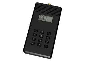
Let’s get into the development of this project, how it works, and what took so darn long. Spoiler - this is going to be a series.
Inception
The basic idea for the FoxSniffer came from a common complaint among my ham friends - there’s not any good options for a handheld RDF tool currently in production. We have big vehicle mounted systems, attenuators and such you can slap on an HT, and the VK3YNG Foxhunt Sniffer MK4 aka the unobtainium blue box.
Those blue boxes are out of production, rarely popping up for sale and always for a high price. Legend says they are made with parts no longer available and the project is defunct. They’re a great tool built on a simple idea - measure the received signal level and make a tone proportional to that level, when the signal is too strong add attenuation to bring it back down. In simple terms it’s an audible S-Meter with an automatic attenuator.
It seemed so simple. A signal strength measurement, some switched attenuation, a speaker, and a microcontroller running the show. With modern parts I should be able to make something better and cheaper than the old MK4.
When someone searches for ‘Hubris’ on QRZ it should just redirect to my page.
Initial Design
The requirements are something like this:
Requirements
- Receive airband ELTs (121.5MHz), amateur 2M (144-148MHz), and amateur 70CM (420-450MHz).
- Work with any modulation (FM, AM, CW, etc).
- Cover a wide range of signal strengths from near the noise floor to standing on top of a well hidden fox (I calculated about 0dBm at the antenna connection for a 5W fox with great antennas).
The initial design sketch took some time. Like most engineering work there’s an infinite set of tradeoffs to analyze. The basic task is to filter out one target signal and measure the signal strength. My thought process went something like this.
RF Section
- Dealing with VHF and UHF I’m going to need to mix to some common frequency. I don’t know how to build variable filters or detectors that can run into UHF.
- If I’m mixing to a common frequency I can use off the shelf filters, e.g. crystal filters. These have very tight passbands and are well understood devices. They can be a bit pricey and impedance matching is unpleasant (their impedance is around 2kOhm).
- Building my own detector sounds fun, it could just be a diode and a capacitor, but that felt risky with my level of experience. I decided on an off the shelf RSSI measurement device instead.
- The mixer, crystal filter, and impedance matching will be lossy. I’ll need an LNA (or several) to bring the received signal into the detector’s range and counter all the losses.
- Strong signals can be handled by switching in attenuation. Attenuation is easy with simple resistor networks wrapped in RF switches to bring them in and out of circuit, nothing really complex, but the switches and other components need to survive the strong signals.
I chose a BGS12P2L6 RF switch, BGB707L7ESD LNA, ADEX-10L+ mixer, YIC 21.4MHz 4-pole crystal filter, and LT5537 RSSI detector. LNAs were placed up front with the attenuator ladder, after the mixer, and after the crystal filter. My math showed I could bring the noise floor (about -120dBm) up into the detector’s range even with all the losses in the circuit. As a bonus that LNA choice could easily be switched between high and low gain levels with a GPIO pin, and in the disabled state it had a forward loss of around 36dB so I could turn off LNAs for additional attenuation if necessary.
That mixer needs a local oscillator. For simplicity I used an SI5351. That device can output any frequency up to 200MHz (and a bit beyond if you’re careful). With the 21.4MHz crystal filter that set my upper limit receive frequency to 221MHz - not quite what I wanted but good enough for a prototype.
Some of you are screaming at your screen trying to tell me about all the things I missed. Don’t worry, I’m getting there.
Everything Else
The rest of the system isn’t challenging. I used an RP2350 MCU to run things (because they’re easy to work with and cheap), added a switch matrix for user input, a small speaker to play the tone, and a character LCD for menus and programming. Nothing complicated.
Bring Up
Here’s where things actually went well. The r0 circuit pretty much just worked. It was my first time creating a switch matrix (a grid of switches allowing for more input buttons than IO pins) and that worked exactly as designed. The display worked fine, although It was difficult to align it perfectly on the PCB. Even the RF circuit came up and did exactly what it was design to do - it just wasn’t well designed.
I used U.Fl connections as probe points. That worked alright but at VHF and UHF frequencies just putting a tap in the middle of a circuit has far too much impact on the measurement. That made testing the filters and finding all the performance issues in the RF circuit very difficult.
Results
Not. Good.
Design Ommissions
There’s a few glaring issues with my design. The biggest being I didn’t include any preselect filters. Unfiltered RF was going to my mixer which means anything at the image frequency would get mixed to the measurement frequency (IF) in addition to my target frequency. This is because mixers work in both up conversion and down conversion, signals at LO + IF AND LO - IF both end up at IF after mixing.
With only a single mixing stage and a 21MHz IF I’d need filters that could pass a target signal but strongly reject signals just 42MHz away. For the receive coverage I wanted that would require dozens of filters and switches to pick the correct filter for a given frequency. Not at all practical.
My next prototype would need multiple mixing stages. With a higher first IF I could have fewer preselect filters, then filter the first IF, and mix to a lower frequency for measurement. This is the classic double conversion heterodyne. Unfortunately it means another mixer, and probably another LNA.
Layout Flaws
Then there are the bad layout choices. I didn’t shield the various signals and sections well. My mixer LO line snaked around my crystal filter into the mixer - and leaked past that filter so the detector was mostly measuring the LO. The detector could hear S9+ signals but not much else.
Pacificon Demo
I showed off the FoxSniffer prototype at Pacificon and even took a few pre-orders. It worked well enough to demonstrate the idea but not well enough to actually use on the fox hunt. That was disappointing to say the least but I got a lot of great feedback on the design.
The biggest curveball was learning that folks wanted the device to actually be a receiver, i.e. they wanted it to demodulate the transmitted audio. I hadn’t even considered this but apparently it’s common to put multiple foxes on the same frequency and rotate through which one is transmitting, using audio as the differentiator. My r0 design could not be easily adapted for this.
Next Steps
After Pacificon I combined my notes, feedback from potential customers and my own testing. Here’s my summary:
- The base needs to be a real receiver. Since we’re targeting a wide range of signal types an SDR makes sense - punt the details to software where we can improve the result without replacing hardware (I am a software engineer specializing in signal processing after all).
- Crystal filters are not worth the expense or the trouble, at least not for this.
- Audio output needs to be stereo, the built-in speaker can be mono but I had multiple requests for demodulated audio on one channel and the audible S-meter tone on the other.
- Multiple mixer stages will be needed to properly select the target frequency from images. This also simplifies the LO design a bit - I might be able to stick with simple devices like the SI5351 instead of designing a higher frequency oscillator.
- My PCB layout needed to be a lot more careful - the EEs in my club gave me plenty of reading material to study before I tried again.
Conclusions
The details on the r1 design and testing of it will be in my next post. I went into Pacificon expecting that I would have r1 designed and out very quickly, there were just a couple minor bugs and I knew how to fix them, but real feedback sent me back to the drawing board for a complete redesign of the RF section.
That’s all for now folks.
73, AI6YM